In pellet mill operations, the mechanical components that directly contact feed or biomass material carry enormous responsibility for the final product's characteristics. Among these components, the roller shell sits at the very heart of the compression process. Its surface pattern—the arrangement, depth, geometry, and spacing of grooves or corrugations across its face—exerts a profound and often underappreciated influence on how pellets form, how consistently they hold together, and how efficiently a mill produces output per unit of energy consumed.

Understanding how different surface patterns on a roller shell translate into real differences in pellet hardness, density, durability, and throughput requires looking closely at the friction mechanics, material flow dynamics, and compression geometry that occur in the narrow gap between roller and die. This article walks through the mechanisms at work, connects surface pattern choices to specific quality and output outcomes, and offers practical guidance for selecting the right configuration for your processing demands.
The Mechanics Behind Roller Shell Surface Patterns
How Surface Texture Creates Grip and Drives Compression
The primary function of any surface pattern on a roller shell is to establish sufficient frictional engagement with the raw material being processed. Without adequate grip, the roller simply slides across the material surface rather than drawing it into the die holes with consistent force. This slippage leads to uneven compression, incomplete die filling, and a final pellet that may be soft, crumbly, or dimensionally inconsistent.
Different surface patterns achieve grip in fundamentally different ways. A corrugated or straight-tooth pattern creates sharp linear contact zones that bite into fibrous or coarse materials, generating high localized friction. A diamond-knurl or cross-hatch pattern distributes contact more evenly across the roller face, which suits denser, finer-particle blends where uniform pressure distribution matters more than aggressive initial bite.
The depth of the grooves or corrugations also plays a role. Deeper patterns increase mechanical interlocking with coarse feed materials, providing strong pull-through force. However, excessively deep patterns can trap material between grooves, causing buildup over time that alters the effective surface geometry and reduces performance consistency. Matching groove depth to material particle size and moisture content is therefore an important part of the selection process.
Material Flow Dynamics at the Roller-Die Interface
When raw material enters the pellet mill, it does not simply slide into the die holes uniformly. The roller shell surface pattern actively shapes how the material is gathered, compressed, and forced into the die. Straight-groove patterns, for instance, tend to channel material in a linear direction, which works efficiently with fibrous biomass or long-fiber animal feeds. This directional channeling prevents excessive lateral spreading and keeps the compression zone focused.
Cross-hatch or diamond patterns, by contrast, create multiple micro-contact zones simultaneously, which spreads the incoming material more uniformly across the roller face. For fine-particle materials such as compound feeds with high starch content, this even distribution helps maintain consistent die filling from edge to edge, reducing the risk of density variation within the same pellet batch.
Material flow at this interface is also affected by the angle of the pattern relative to the roller's rotational axis. Patterns with a slight helical offset relative to the die can subtly influence how material migrates toward or away from the die center during operation, which in turn affects die wear patterns and long-term output consistency. Engineers and mill operators who understand these flow dynamics can anticipate output behavior and select a roller shell pattern that sustains stable throughput over time.
Surface Pattern Types and Their Direct Impact on Pellet Quality
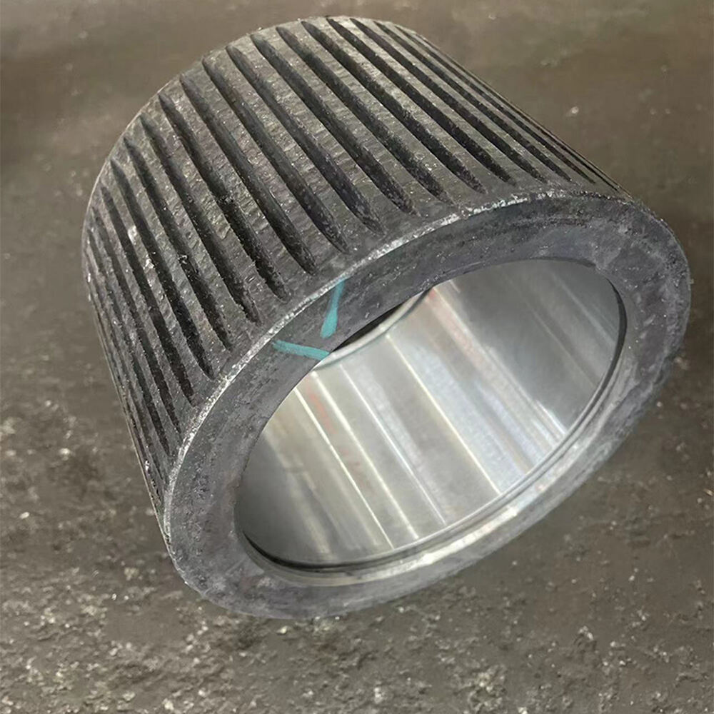
Straight-Tooth Patterns and Pellet Density
The straight-tooth roller shell is one of the most widely used surface configurations in the pellet manufacturing industry. Its parallel ridges run perpendicular or at a defined angle to the roller's rotational axis, creating consistent linear contact lines with the material bed. This configuration is particularly effective at generating high compressive force per unit of roller face area, which translates directly into denser, harder pellets with lower moisture content after pressing.
For applications such as livestock feed, aquaculture pellets, or wood biomass pellets where pellet hardness and durability index (PDI) are critical quality benchmarks, the straight-tooth pattern delivers reliable performance. The defined linear grooves prevent surface glazing—a condition where the roller face becomes too smooth from wear and loses its grip—faster than finer-pattern alternatives, which extends service intervals and maintains pellet density consistency throughout the roller's usable life.
However, straight-tooth patterns are not universally optimal. When processing very fine powders or materials with low inherent cohesion, the linear grooves may not provide sufficient lateral stabilization of the material bed, allowing minor spreading that reduces compression efficiency. In these cases, a roller with a more complex surface topology may be preferable.
Corrugated and Diamond Patterns and Pellet Uniformity
Corrugated roller shell designs with wave-form or sinusoidal profiles offer a different compression characteristic. Rather than applying peak force at sharp linear ridges, the corrugated surface distributes force more gradually and continuously. This softer compression onset reduces shear stress at the pellet surface, which is important when processing materials that are prone to cracking under abrupt pressure, such as certain aquafeed formulations or pharmaceutical-grade pellets.
Diamond-knurl patterns provide the broadest distribution of contact points and are associated with high pellet uniformity in terms of diameter and length consistency. The multi-directional engagement of a diamond surface pattern also reduces the tendency of the material to rotate or slip laterally under the roller, which is a subtle but meaningful contributor to pellet geometric consistency. For mills where output appearance and dimensional tolerance are part of the product specification, a diamond-pattern roller shell can reduce rejection rates at inspection.
The trade-off with corrugated and diamond patterns lies in their susceptibility to clogging with fibrous or sticky materials. When long-fiber biomass or high-fat compound feeds are processed, material can pack into the relief areas between knurls, gradually reducing effective grip. Regular cleaning cycles and appropriate material preparation help mitigate this, but it is a practical operational consideration that operators should factor into pattern selection.
How Surface Patterns Influence Throughput and Energy Efficiency
Grip Efficiency and Productive Throughput
Output volume in a pellet mill is not solely a function of die hole count or motor power. The efficiency with which the roller shell transfers energy into productive material compression—rather than dissipating it through slippage or excess friction—is a direct determinant of how many kilograms of finished pellets the mill can produce per hour. A well-matched surface pattern minimizes wasted motion and keeps the compression cycle tight and productive.
When a roller shell pattern is too aggressive for the material being processed, the overgrip can cause the roller to drag material unevenly, creating irregular pressure peaks that overload certain die sections while underloading others. This uneven loading leads to die fatigue, increased maintenance frequency, and throughput inconsistency. Conversely, a pattern that is too mild for coarse or fibrous materials results in insufficient grip, slip losses, and reduced effective throughput despite the same theoretical mill capacity.
Experienced operators often find that switching to an appropriately matched roller shell surface pattern for a given material formulation can improve throughput by meaningful margins without any changes to motor speed, die specification, or feed rate. This reinforces the point that surface pattern selection is a high-leverage operational decision, not merely a standard replacement choice.
Wear Rate, Service Life, and Sustained Output Consistency
The geometry of a roller shell surface pattern also determines how the component wears over its service life and how that wear affects output quality over time. Patterns with sharp angular peaks—such as aggressive straight-tooth designs—tend to lose their peak geometry relatively quickly under abrasive conditions, transitioning to a smoother effective surface. If the initial pattern is sized correctly, this wear progression can actually improve pellet surface finish in the mid-life stage before grip loss becomes significant.
Patterns with broader contact faces and shallower relief depths wear more gradually and predictably, maintaining a more stable effective surface geometry across the full service interval. This translates into more consistent pellet quality over time, which is especially valuable for operations with strict product specification windows or long production runs between maintenance shutdowns.
Monitoring wear progression on the roller shell is also important because worn surface patterns begin to contribute to increased energy consumption per unit of output. As grip diminishes, the mill compensates through increased roller pressure or reduced feed rate, both of which raise specific energy consumption. Tracking pellet quality metrics alongside operating parameters can help identify the point at which a roller shell replacement is economically justified before it leads to significant output degradation.
Matching Surface Pattern to Application Requirements
Material Properties That Drive Pattern Selection
The right roller shell surface pattern for a given application depends heavily on the physical and chemical properties of the input material. Moisture content is one of the most critical variables. Higher-moisture materials tend to be more plastic and compressible, which means they respond well to moderate-grip patterns that apply progressive pressure. Very dry, brittle materials require more aggressive grip to initiate compression before the material fragments under sharp loading.
Particle size distribution matters as well. Fine, homogeneous materials flow into die holes more readily and benefit from uniform distribution patterns on the roller shell. Coarse, heterogeneous materials with wide particle size ranges need stronger bite and channeling capability to maintain consistent compression across the die face.
Fat content in compound animal feeds is a particularly important consideration. High-fat materials are naturally lubricating, which reduces friction at the roller-die interface. For such formulations, more aggressive surface patterns that compensate for fat-induced lubrication are essential to maintain acceptable pellet quality and prevent throughput loss. A roller shell specified without considering fat content can underperform significantly in high-fat feed applications.
Production Goals and Quality Specifications
Beyond material properties, the intended end use of the pellets shapes the optimal pattern choice. Aquafeed manufacturers who need water-stable, sink-rate-controlled pellets require very high compression consistency, which favors patterns that produce even, high-density pressing across every die hole. Biomass fuel pellet producers who prioritize throughput volume over dimensional precision may accept more variation in pellet density and benefit from patterns designed for maximum material pull-through speed.
Pet food pellet production often involves both high-temperature steam conditioning and precise texture requirements, where the roller shell pattern must perform well with thermally modified starches that behave differently from raw feed mixes. The pattern selection here needs to account for the post-conditioning material's increased plasticity and tendency to adhere, making smooth-release geometry between contact ridges important for preventing surface defects on the finished pellet.
In all application scenarios, aligning the roller shell surface pattern with both material characteristics and target product specifications is the foundational decision from which all other pellet mill adjustments—gap setting, die compression ratio, feed rate—derive their effectiveness. A mismatched roller pattern creates a constraint that no downstream adjustment can fully compensate for.
FAQ
What is the most common roller shell surface pattern used in feed pelleting?
Straight-tooth and corrugated patterns are among the most commonly used configurations in feed pelleting operations. The straight-tooth roller shell is preferred for fibrous materials and applications requiring high pellet hardness, while corrugated patterns suit finer, more cohesive formulations where uniform compression distribution is prioritized. The optimal choice always depends on the specific feed formula and target pellet specification.
How does roller shell wear affect pellet output quality over time?
As a roller shell wears, the surface pattern loses its defined geometry, reducing grip efficiency and increasing slippage at the roller-die interface. This wear progression initially may have minimal impact, but as it advances, pellet density decreases, throughput drops, and energy consumption per kilogram of output rises. Regular monitoring of pellet quality metrics is the most reliable way to track effective wear and time replacement correctly.
Can the same roller shell surface pattern be used for both biomass and animal feed pelleting?
While some general-purpose roller shell patterns can be used across both applications, the performance trade-offs can be significant. Biomass pelleting typically involves dry, fibrous materials that benefit from aggressive straight-tooth patterns, whereas compound animal feeds often contain fats, starches, and moisture that require different friction and compression characteristics. Using application-specific patterns for each material type generally yields better pellet quality and longer component service life.
How frequently should a roller shell be inspected or replaced?
Inspection frequency depends on the abrasiveness of the material being processed, operating hours, and the metallurgical specification of the roller shell. As a general guideline, surface pattern depth and geometry should be assessed visually after significant production runs, and quantitative pellet quality measurements such as durability index and bulk density should be tracked as leading indicators of roller condition. A noticeable decline in these metrics, combined with increased energy consumption, typically signals that the roller shell has reached the end of its productive service life.
Table of Contents
- The Mechanics Behind Roller Shell Surface Patterns
- Surface Pattern Types and Their Direct Impact on Pellet Quality
- How Surface Patterns Influence Throughput and Energy Efficiency
- Matching Surface Pattern to Application Requirements
-
FAQ
- What is the most common roller shell surface pattern used in feed pelleting?
- How does roller shell wear affect pellet output quality over time?
- Can the same roller shell surface pattern be used for both biomass and animal feed pelleting?
- How frequently should a roller shell be inspected or replaced?